Digital Logic Vending Machine
This project is one of the more impressive hardware projects that I have had the opportunity to undertake at Tufts so far (although Junior and Senior design are fast approaching). The goal of the project was to create a vending machine circuit using digital logic and other analog circuit components. The vending machine was required to: display the amount of money inserted into the machine, play a tone when a coin is inserted, play a melody when the price of a soda ($2.50) is reached, indicate that a soda should be dispensed, display up to 50 cents in change after $2.50 is inserted into the machine, and reset to its initial state 3 seconds after $2.50 is inserted.
The Assignment
We were tasked with creating a circuit that performed all of the functions of a vending machine.
The Result
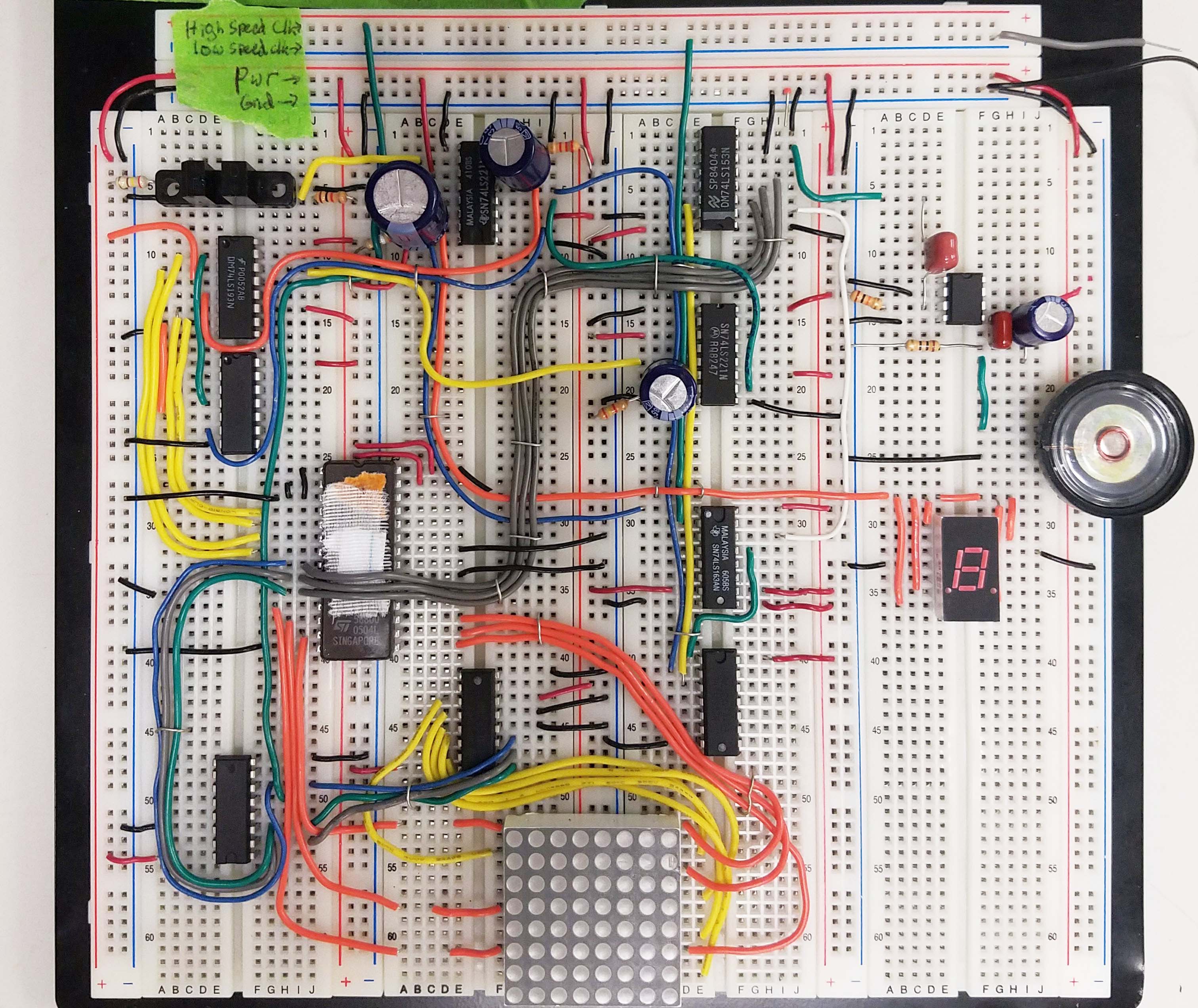
A circuit that can count the amount of change inserted, display it, notify the user, and more...
Skills
- Logical Circuit Design
- EPROM Programming
- VHDL Simulation
- Op-Amp Configuration
- Circuit Debugging
Design Process
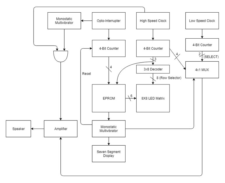
Even though the design constraints of the system were fully laid out for us going in, we had quite a bit of flexibility in how we implemented our solution. We had to esign the system from scratch, using what we had learned that semester, and order the specific parts we needed from the TAs. We began by thinking through each individual function and what systems would be required to implement them. This led us to creating a very simple block diagram which we then turned into the schematic below. This schematic then became our guide for the remainder of the project. Once we created the schematic, we moved on to simulation of the major systems in VHDL. This gave us great insight into how these systems would work in the final circuit and how to best interconnect them.
Components and Systems
Although this project was based primarily around digital logic, there were quite a few places during the design where my knowledge of analog systems also came into play. For example, we needed an amplifier to effectively drive the speaker. To create this amplifier, we used a correctly configured opamp and highpass filter to remove DC offset and protect the speaker. Another component that leveraged my knowledge of analog systems was the Monostatic Multivibrator delay circuit. Correctly choosing capacitors and resistors to give the correct RC constant and the correct delay was essential to the final function of the circuit.
Challenges
The primary chalenges while designing and implementing this system were getting over the initial design hump and debugging the finished circuit. With few details on how to implement the system going into the project, there was the "oh crap, how do we do this" moment. That didn't last long, however, as our group broke down the overall project into its different systems and decided how to implement each one. In this way, we were able to efficiently tackle a project that at first seemed daunting. The other major challenge was that of debugging the finished circuit. With such a complex circuit, there were many things that could and did go wrong, from bad multivibrator chips to faulty EPROMS, to bad breadboard connections. These problems were easily tackled, however, through careful verification of each component's operation and lots of time with the oscilliscope.
Takeaways
In the end, we created a final circuit that solved all of the design problems and worked like a charm. Unfortunately I can't release the final report due to academic integrity concerns but if you would like to know more, don't hesitate to reach out via email (below). I learned quite a bit throughout this project but my main takeaway is how best to break down a digital design project into it's simpler systems and then combine these systems together to make the complex final product.


Copyright © 2024 Chris Markus